Welding blueprint symbols are essential for communicating welding instructions clearly and accurately. Understanding these blueprints is crucial for welders and engineers to ensure high-quality welds and avoid errors.
This guide will provide a detailed explanation of the common welding blueprint symbols and signs, along with examples and options for each aspect of the welding symbol.
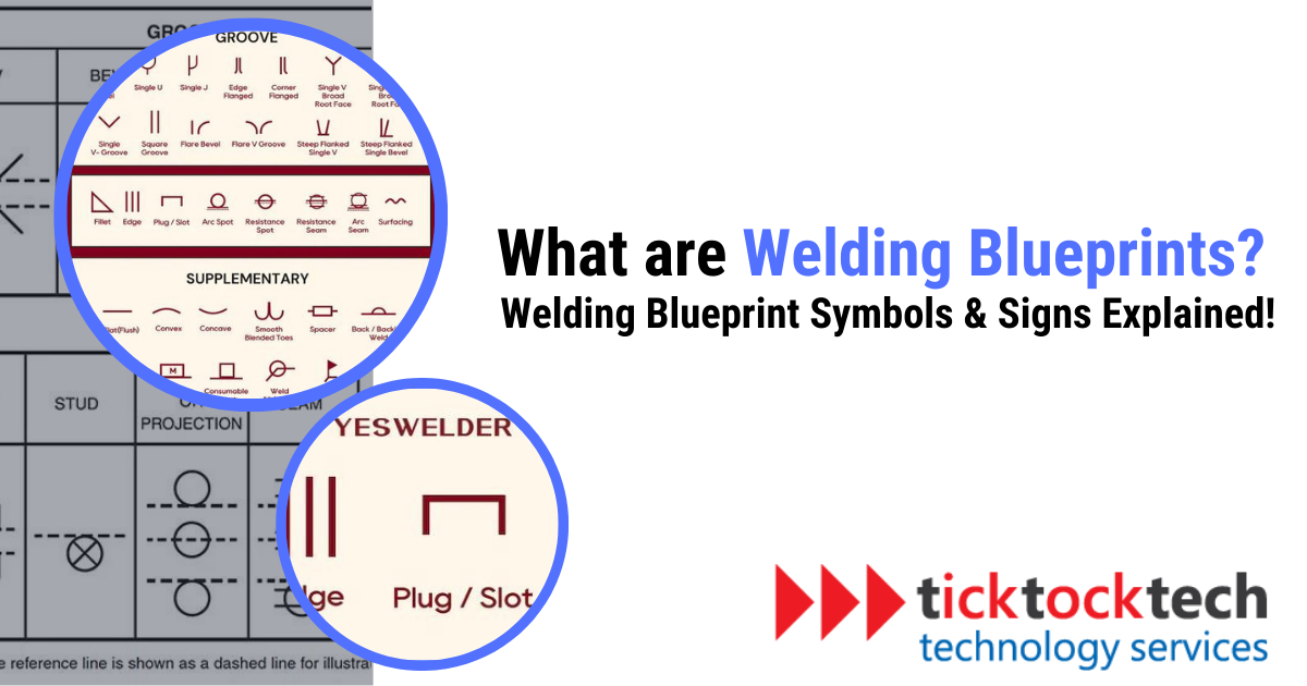
What are Welding Blueprint Symbols?
Welding blueprint symbols act as a communication bridge between a designer (like a workshop manager, welding engineer, or supervisor) and a welder. These symbols depict the weld type, size, and other processing and finishing details. Welding blueprint symbols are found on engineering and manufacturing drawings, which serve as a reference for the welder.
In the welding industry, the 1/16th rule is a standard. This rule allows welds to deviate from the specified size by no more than 1/16th of an inch. Given the importance of accuracy in this field, understanding and following blueprints is crucial for welders to produce welds that meet standards.
Before starting a weld, welders often refer to a Welding Procedure Specification (WPS). This document provides guidance on material thickness, the general welding position, and the electrodes to use. After consulting the WPS, the welder turns to the welding blueprint. This blueprint, containing weld symbols and specific measurements, provides the necessary information to complete the task. These blueprints come in different formats, including isometric, orthographic, and 3D.
There are several welding blueprint symbols, each representing a different type of weld. While not used in every industry, these symbols are common in industries like construction, where parts must meet exact specifications. In such sectors, welders rely on blueprints daily to guide their work.
Understanding the Basic Structure of a Welding Symbol
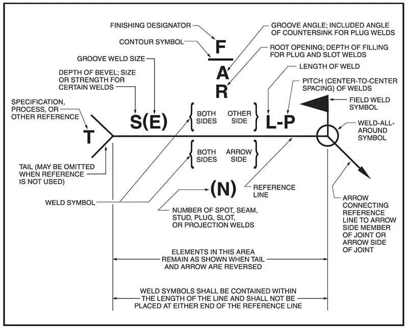
The American Welding Society outlines what a welding symbol is composed of. The skeleton of the welding symbol consists of a horizontal line, the reference line, which serves as an anchor and represents the axis of the weld. Along this reference line, an arrow connects to show the joint that is to be welded.
In addition to the reference line and arrow, welding symbols may include other elements to provide specific information about the welding process. These elements include notes or details, specifications, codes, standards, or other drawings that eliminate the need for additional symbols.
The tail of the welding symbol designates the welding, brazing, or cutting process, as well as other specifications or procedures. All elements within a welding symbol have specific locations, as shown in the image below:
Welding Symbols and their Meanings
Welding symbols are standardized designs that convey detailed instructions for the welding process on blueprints or plans. Each symbol provides specific information about the type of weld, dimensions, and other requirements. Here is a comprehensive list of what one can expect to see on a welding symbol:
1. The Arrow
The arrow serves as a guide, pinpointing the exact weld location. It has a reference line attached to its body, displaying important welding details.
2. The Arrow Head
This part points right at the specific location to be welded on the drawing. While not always straight, it may slant to highlight the exact weld spot based on the structure’s shape.
3. Circle Injunction
The circle injunction, also known as the ‘all around weld symbol,’ indicates the need to weld around the entire circumference of round geometries. It signifies the need to weld every part of the joint. However, on non-circular joints, this symbol may not be present.
4. The Flag
The flag symbol on a welding symbol indicates the location of the welding activity. A present flag means field welding is required. Without the flag, welding takes place in a workshop. This distinction is crucial as welding conditions vary based on the working environment.
5. The Reference Line
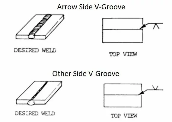
The reference line is a crucial component containing detailed weld information, such as joint design, weld pattern, and size. It can be double-sided or single-sided, indicating different weld types for the top and bottom sides. If there is no bottom side indicated, only the top side will be welded, and vice versa.
6. Groove Design
Groove design varies across welding joints, with each design specifying a particular groove weld symbol. Commonly seen designs include the fillet weld and V-Groove. Other designs like the X Groove, I-Groove, and U-Groove also play significant roles in welding tasks.
7. The Weld Size
The weld size refers to the dimension of the completed weld, impacting its strength and part distortion during welding. Two main callouts are used: S for size, commonly seen in fillet welds, and E for the effective throat, primarily used in groove welding.
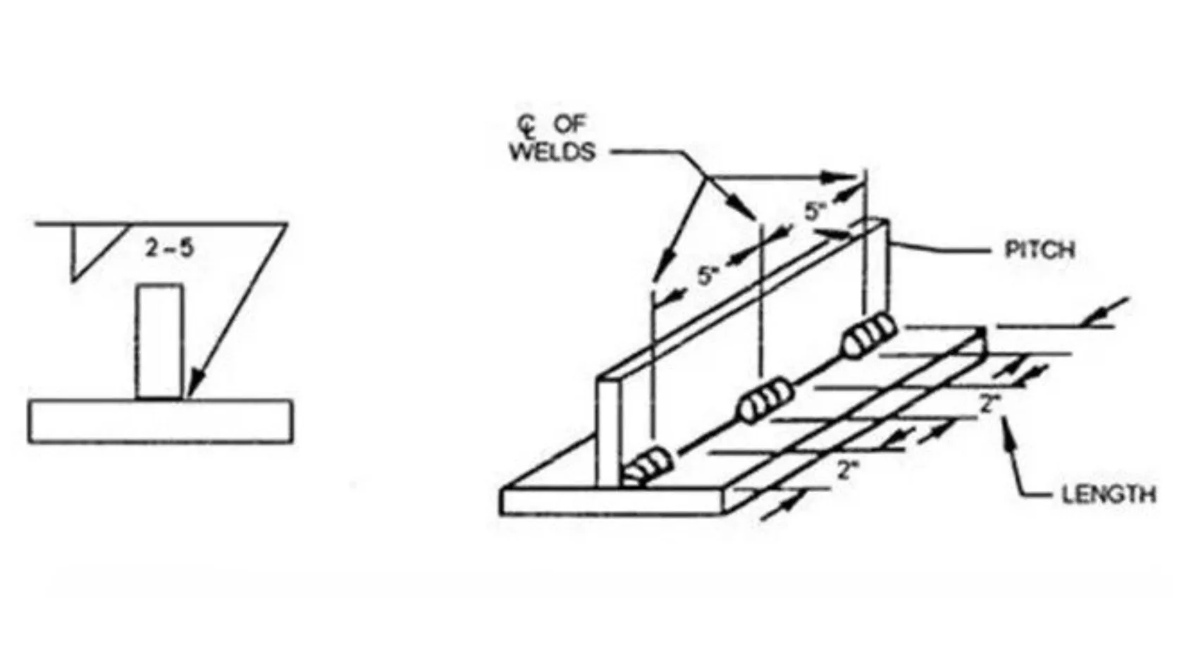
8. The Weld Pattern
Most welds are full length, so the weld pattern rarely features in welding symbols. It details the pitch (center-to-center distance, P) and length of each weld seam. You use weld patterns to address concerns of distortion or excessive material consumption.
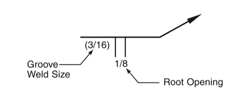
9. The Root Opening
The root opening symbol marks parts requiring a root-pass weld, where you create a gap between parts for full penetration welding. This technique is commonly applied in pressure vessel applications.
10. The Bevel Angle
The bevel angle shapes the joint’s edge where two parts meet for welding. It influences weld depth and quality for effective joins.
11. The Contour
The contour specifies the weld’s final shape, whether convex (rounded outward), concave (U-shaped), or flush (even with the joint surfaces). It also hints at the required finishing method.
12. Finishing
The finishing directive complements the contour by indicating the method for achieving the contour’s shape: machining (M), surface grinding (G), or chipping (C).
13. The Tail Welding Symbol
The tail welding symbol holds extra details not included in the main symbol. It covers post-weld inspections, specific procedures, and any additional welding information required.
How to Read Welding Blueprints
There are six basic types of welds, each with its own distinct symbol:
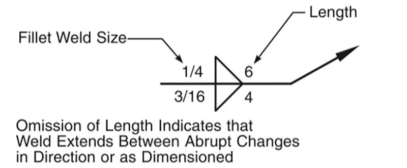
1. Fillet
The widely recognized fillet weld symbol is used for corner joints, lap joints, and T-joints, appearing as a triangular shape that isn’t always isosceles or right-angled. Aligning two members allows for depositing weld metal in the corner, which then penetrates and fuses with the base metal, creating a strong joint.
2. Groove
Groove welds create edge-to-edge connections and are also common in T joints, corner joints, and unions between flat and curved surfaces. The method of welding varies with the parts’ shapes and how their edges are prepared. In this process, you fill the groove with weld metal, which then bonds with the base metal to secure the joint. Groove welds come in several forms, including square, double-bevel, and V-groove types.
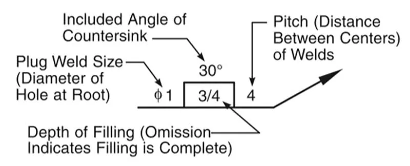
3. Plug or Slot
Plug and slot welds connect overlapping parts by drilling holes, with plug welds having round holes and slot welds having slot-shaped holes. Weld metal is then deposited in the holes, fusing with the base metal to form the joint.
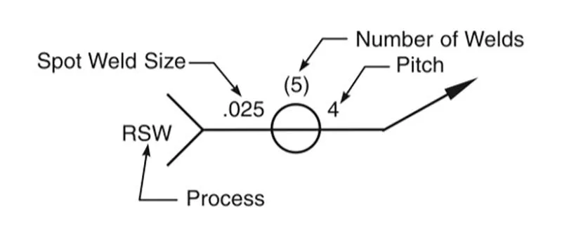
4. Spot
Spot welding connects overlapping metal sheets at precise points, utilizing pressure and electric current. Initially, electrodes touch the metal surfaces to join, applying pressure. Subsequently, an electric current passes through the electrodes, melting the contact points. After removing the current, the electrodes remain until the metal cools and solidifies, completing the connection.
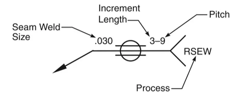
5. Seam
A seam weld is comparable to a spot weld in terms of the welding process. In a seam weld, the weld penetrates the top surface and fuses with the other part through the application of heat. The symbol for a seam weld is similar to that of a spot weld, but it features two parallel lines running through it.
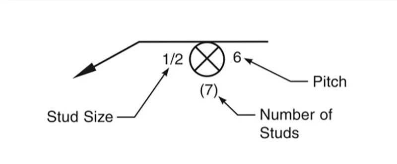
6. Stud
Stud welds are used in many workshops as a reliable fastening method. This process involves heating a metal stud and a metal workpiece using an electric arc. The heat causes the stud to bond securely with the workpiece, creating a strong connection.
Frequently Asked Questions about Welding Symbols
Conclusion: Welding Blueprint Symbols & Meanings
Welding blueprint symbols and signs are crucial for communication in design and engineering. They provide a universal language that enables professionals to accurately represent various types of welds and weld joints on technical drawings, ensuring a seamless transition from design to production. By utilizing these symbols and specifications, professionals can ensure the quality and safety of the final product, contributing to the overall success of projects.